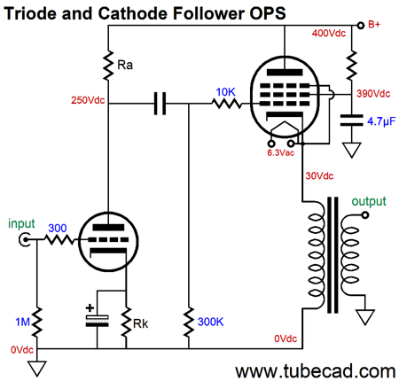

What is the best-case scenario for an audio power amplifier? Answer: a sinewave generator providing a single-frequency, fixed-amplitude input signal and an 8-ohm resistor as the load. Like so many theoretical conclusions, however, the underlining assumption is of a best-case scenario. Why? Theoretically, one global negative feedback loop will always result in less distortion than two separate negative feedback loops in series. Two-stage power amplifiers have made many appearances here before, but are probably nonexistent elsewhere. For example, we can use this circuit as the first stage of a two-stage power amplifier, with each stage holding its own negative-feedback loop of course, second stage would be push-pull power amplifier, which could the form of a circlotron output stage or the more conventional push-pull transformer-coupled version. The negative-feedback phase splitter, however, finds a wider application than just tube-based equalizers. With a gain of 20dB, 1Vpk of unbalanced input signal would become +/-10Vpk of balanced outputs, or +/-20Vpk of differential signal. Indeed, setting a gain of 20dB (1:10) is easily achievable with common audio small-signal tubes, such as the 12AT7/ECC81 or 12AY7 or 12AX7/ECC83. This phase-splitter design was meant to fill in the hole left by the absence of a balanced input signals, such as those provided by the XLR jacks on the back of many DACs.Īs we are not limited to unity gain, we alter the negative feedback loop resistors to develop gain. In the last post, we saw a unity-gain phase splitter that held its own negative feedback loop, which resulted in a fixed gain and lower output impedance-and with a dollop of Aikido mojo, improved PSRR. valves).Ĭapacitors over 100♟ and 450V were the stuff of dreams. In 1938, capacitors were not cheap, nor were resistors and tubes (i.e. Without feedback and 0.55 to 0.22 volt with The hum output from 0.72 volt to 0.33 volt With hum measured at the 6F6G output is not so noticeable due to the variety ofĬauses. Of 1.4 volts, this average taking account ofĪmplifier with feedback, the improvement obtainable Hum in the output was reduced to an average Volts hum in the supply voltage, 5.6 volts appearedĪ suitable value of C1 this could be neutralised,Īnd it was found that by using 0.05 ♟.

Reduced hum voltage being passed on to theįollowing stage. Plate supply voltage will result in a somewhat Represents a resistance coupled pentode A.F. One very simple way in which neutralisation To maintain correct balance due to variations Optimum neutralisation is obtained it may fail Neutralisation does not usually result inĬomplete elimination of the hum due to phaseĭifference and harmonics, and even if initial Paul has unearthed the first example of Aikido mojo.Ī pentode's grid-2 receives an inject of some of the power-supply, which then forces a noise null at the plate.Īvoiding hum is to use sufficient filtering, thereĪre occasions when any increase in filtering isĪdopted to reduce the annoyance. Thanks to reader and patron, Paul Reid, for sending this my way.


 0 kommentar(er)
